
Configuring Multicast has always been one of the challenging tasks for many network admins, since it is not a common application requirement for enterprise networks. On the other hand, service providers are using multicast in services such as video and audio streaming.
Multicast is network traffic which is intended to specific “interested” end-points and hence multicast routing protocols work in a different way than conventional unicast routing protocols.
In unicast networks, first routing information is being exchanged by routing protocols (OSPF, BGP, static …) and then traffic can flow accordingly. In multicast networks on the other hand, the traffic first flows into the network and then the routing information and best routes to multicast sources and destinations (multicast trees) are built and shared by means of multicast routing protocols.
Multicast routing protocols
There are various multicast routing protocols however the most commonly used protocol is Protocol Independent Multicast (PIM) and even though it works differently in terms of route learning than unicast routing protocols, its main function is to route multicast traffic optimally to interested multicast receivers.
Multicast groups and group joining protocols
Multicast address groups has a defined IANA range from 224.0.0.0 through 239.255.255.255. This is called a group address, so any application that will be utilising multicast to communicate to group of “interested” listeners will need to stream the multicast traffic to a group address. The “interested” listeners will need to then “join” this multicast group to show their interest in receiving the streamed multicast traffic on that specific multicast group address.
In order for the “interested” listeners (hosts or routers)to show there interest in joining a particular multicast address group, they need to use a protocol called IGMP (Internet Group Management Protocol).
IGMP join messages are used by interested receivers to show their interest in joining a multicast group, routers which receives this information will then forward any multicast traffic with that group destination address to hosts or other peer routers who are interested to receive that multicast.
Lab Inventory
For software versions I used the following:
- VMware ESXi, 7.0.2, 17867351
- vCenter server version 7.0.3
- NSX-T 3.2.0.1
- TrueNAS 12.0-U7 used to provision NFS datastores to ESXi hosts.
- VyOS 1.1.8 used as lab core router.
- Two Ubuntu 20.04.2 LTS VMs as multicast sender and receiver.
- Ubuntu 20.04.2 LTS as DNS and Internet gateway.
- Ubuntu 20.04.2 LTS as Linux management host.
- Windows Server 2012 R2 Datacenter as management host for UI access.
For virtual hosts and appliances sizing I used the following specs:
- 2 x virtualised ESXi hosts each with 8 vCPUs, 4 x nics and 32 GB RAM.
- vCenter server appliance with 2 vCPU and 24 GB RAM.
- NSX-T Manager medium sized deployment with 6 vCPUs and 24 GB RAM (no reservations).
Lab Topolgy

In the above topology I have the multicast sender VM connected to a T1 gateway through segment 100.100.100.0/24 and on the left side the multicast destination VM connected to another T1 gateway through segment 200.200.200.0/24.
Both T1s are connected to a T0 which will be forwarding the multicast traffic across the two subnets. Since in my lab setup I do not need to forward the multicast traffic to another T0 or over the core physical network, I will not be running any multicast routing protocols on the T0.
Before we start configuring multicast we need to ensure that we have a fully prepared cluster with NSX for networking and security, an edge cluster and an overlay transport zone.
Deploying segments, T1 and T0 gateways and enabling multicast
First. we need to create 2 x logical segments and connect our multicast source and destination VMs to them accordingly. There are no specific multicast configuration that needs to be done on the logical segment level.
Below are the segments I created for both VMs

Before creating our T0 and T1 gateways we need to create an IGMP profile. From the NSX UI navigate to Networking and from the left pane under Settings click on Networking Profiles and on the left click on Multicast and then ADD IGMP PROFILE. I created an IGMP profile with just the default values, since in a lab environment you do not really need to tweak any protocol timers.

I assume that since you are reading this blog post you probably know how to configure a T1 and a T0 router and link them to segments. If not, then I highly recommend revising VMware NSX-T documentation first and learn the difference between both gateway types and how to configure each type. If you are familiar with both types and understand the difference between them then keep reading.
Create two T1 gateways and a T0, connect the above created segments (source and destination) to corresponding T1 gateways and then link both T1s to your T0.
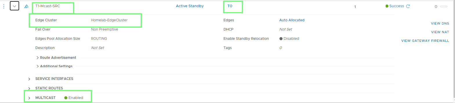
On your T1 gateways you just need to enable multicast and attach your T1s to an edge cluster

On your T0 you need to do some extra configuration to enable multicast, see below a screenshot with the highlighted section of the multicast configuration

Note that the IGMP profile is a must while PIM is not. As mentioned earlier I do not need to run any multicast routing protocol in my lab as the multicast traffic will not be leaving the configured T0 gateway.
It is important to mention that the multicast replication range address that you need to specify (239.1.1.0/24 in my example) has nothing to do with the group address that you will be using for your multicast traffic. This range is needed by NSX for multicast communication in the overlay (GENEVE destination address).
Important note, In my setup I did not need to enable multicast on the T0 external uplink interface, this is again due to the fact that I am using a single T0 connected to both T1s and no multicast traffic will be leaving the T0 gateway. If in your case you need to propagate the multicast traffic to another T0 or through the external network then you need to have multicast enabled under the external T0 interface configuration.
Testing multicast traffic
As I have prepared my NSX-T network to allow multicast traffic between the source and destination segment VMs, we need to test by generating a multicast traffic from the source VM (address 100.100.100.10) to destination VM (address 200.200.200.20).
First we need to login to our vCenter and connect the vNIC of each VM to the corresponding NSX-T logical segment. Right click the VM and choose Edit Settings then connect the network adaptor to the source or destination segment.

For the destination VM

Generating and receiving multicast traffic on my test VMs
For this purpose I used iperf as traffic generator tool. If iperf is not installed on your source and destination VMs then you need to install it before continuing. iperf is available for windows and Linux operating systems, in my lab setup I am using Ubuntu 20.04 LTS as multicast source (sender) and receiver (listner).
On the multicast destination (receiver) VM start an iperf session to join a multicast group:
mcastdst:~$ iperf -s -u -B 224.1.1.1 -i 1
------------------------------------------------------------
Server listening on UDP port 5001
Binding to local address 224.1.1.1
Joining multicast group  224.1.1.1
Receiving 1470 byte datagrams
UDP buffer size:  208 KByte (default)
---------------------------------------------------
On the source (sender) VM use iperf to generate multicast on group address 224.1.1.1
mcastsrc:~$ iperf -c 224.1.1.1 -u -T 32 -t 3 -i 1
---------------------------------------------------
Client connecting to 224.1.1.1, UDP port 5001
Sending 1470 byte datagrams, IPG target: 11215.21 us (kalman adjust)
Setting multicast TTL to 32
UDP buffer size:  208 KByte (default)
------------------------------------------------------------
[  3] local 100.100.100.10 port 38259 connected with 224.1.1.1 port 5001
[ ID] Interval       Transfer     Bandwidth
[  3]  0.0- 1.0 sec   131 KBytes  1.07 Mbits/sec
[  3]  1.0- 2.0 sec   128 KBytes  1.05 Mbits/sec
[  3]  0.0- 3.0 sec   385 KBytes  1.05 Mbits/sec
[  3] Sent 268 datagrams
Now switch back to the listener VM, you should see a similar output to the below:

The above shows that listener VM has successfully received traffic on the multicast group address 224.1.1.1.
